I've been busy with work during the month of July so getting things done on the boat has been a challenge. But I did finally finish the new cockpit table and get the Garmin GPS installed. We also have a new 120% genoa aboard, but haven't set it up on the furler yet. Lastly we took the liferaft and MOM unit in for servicing.
The reason for the new cockpit table is that the original one took up too much space and we got tired of it being in the way. The new arrangement works much better for actually sailing the boat and provides a place for the new GPS.
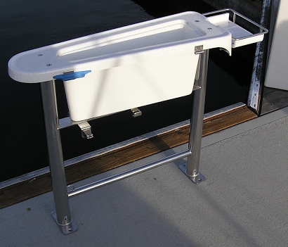
The process began with removal of the original table. The photo below shows the standard arrangement for the B423. You can see that it pretty much fills up the cockpit forward of the steering pedestal. It is fitted with large drop-leaves that make for a very spacious dining table when they are deployed and for many B423 owners it's a good arrangement.
 |
| The lid fits loosely on the table and encloses a deep stowage bin. Notice the slip pin hinges for the drop-leaves. |
 |
| Plenty of room with the table removed |
Removing the table reveals the spaciousness of the cockpit. I filled in the holes left by the mounting bolts. Later I installed a teak foot rest which concealed them. The table legs are nicely made of stainless steel and are plenty strong so I kept them for use on the new table.
 |
| Table base incorporates a solid, if slippery footrest. The blue tape covers the forward hinge which had an uncanny ability to snag clothing. |
The next step was to mock up the new table. I wanted it to be smaller than the original table, incorporate the new GPS and provide solid hand-holds. I took a template off the forward side of the pedestal and entered those dimensions into the computer because I wanted the new table to follow the contours of the pedestal. Then I played around with different shapes until I had something that looked like it would work. I made a mockup out of particle board and check fitted it.
 |
| Particle board mockup. |
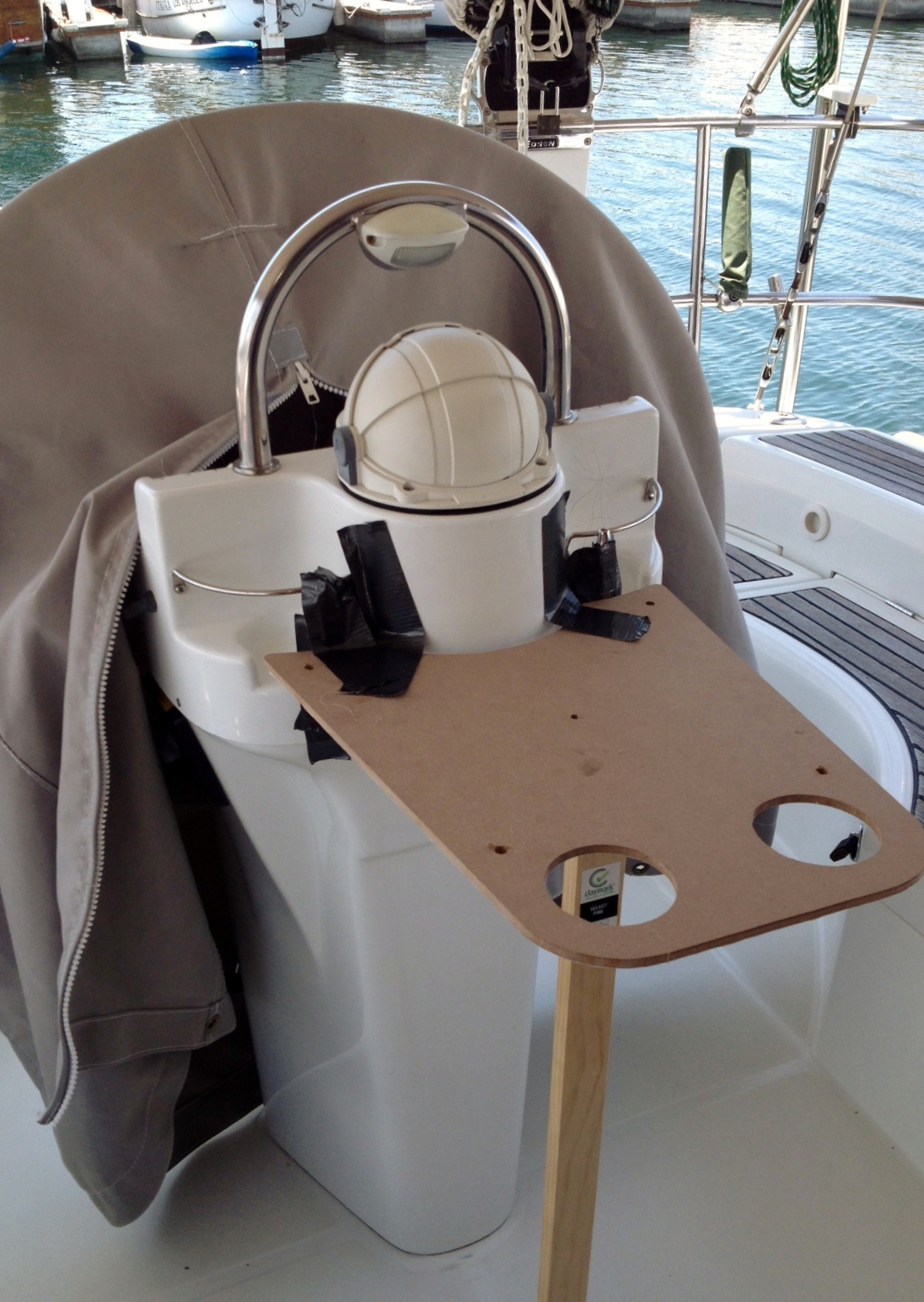
The new shape looked good, but the original table leg assembly was not tall enough. I wanted the table to be high enough that we could see the new GPS even when standing at the wheel. So while the leg assembly was in the shop getting modified I laminated up a mahogany riser and fabricated the table itself out of 3/4" StarBoard.
 |
| The mahogany riser puts the table at a convenient height. The post that the GPS is mounted on can be adjusted for height and it swivels. The cable is routed down through the post and fed into the starboard table leg. From there it passes through the deck and into the aft cabin. |
With the GPS mounted high enough for good visibility from the helm, it was too high to be convenient when sitting in the forward part of the cockpit, which is why I incorporated a pedestal that can be adjusted higher or lower and swivel for good visibility from anywhere in the cockpit. When we're at sea, we almost never stand or sit at the helm. When you're on watch alone, the autopilot will always do a better job of steering the boat than a human over the span of an entire watch. The best place to stand watch is in the shelter of the dodger. On the Beneteau 423 that presents a problem because all of the instrumentation and controls are on the "dashboard" at the helm. The new GPS solves the navigational aspect of the problem and it will display AIS information as well. The handheld remote for the autopilot substitutes for the controller at the helm. The new TackTick sailing instruments are wireless and the displays can be located anywhere. So with this system in place we can navigate and control the boat from the most comfortable spot in the cockpit. This gets real important when you're punching into a head sea on the midnight watch and you're the only person on deck for three hours on a windy and moonless night.
 |
| On the left is a 2011 Santa Margherita Pinot Grigio, to the right is a 2009 Cakebread Cabernet. |
Once the unit was installed we had to check fit the drink holders. They worked like a champ! I have been planning to add a fold-down dining table which would be attached to table leg assembly but for now, we're pretty pleased with the current arrangement.
The Rescue Pod
 |
Switlik Rescue Pod 4
Switlik refers to it as an "Emergency Floatation System" rated for 4 people. It would be extremely cozy for four, but reasonable for two. |
Finisterra has a Switlik Rescue Pod for a liferaft, which is fine for coastal cruising in the temperate and tropical regions where the Finisterra will be traveling. It was time for a checkup so I took it to Avalon Rafts in Wilmington, California. Everyone who owns a raft or races offshore has taken a Safety At Sea course and seen raft deployment demonstrations, so you have a general idea of how they work and how they are equipped. But few of us have deployed our own raft, so we hung around and went through every detail of our little pod. It was something of an eye opener to see exactly how it works, what happens when things go wrong, and what the equipment bag really has in it. It has caused me to revise the equipment and supplies we carry in our ditch bag and I feel a lot more prepared in case we ever have to deploy the raft in a real emergency. If you plan to do any truly offshore work, one look at the Pod when it's deployed will convince you to opt for a real liferaft.
The Pod is, as you can see in the photos, basically a flat disc. That means that in has a 50% chance of inflating upside down. It has a righting line across the bottom, so it can be righted, but if you have a Pod, keep in mind that the first thing you may be required to do once you've launched it, is to get in the water and pull the thing upright. It looked pretty easy in the comfort of Avalon's shop. It might be a different story in 15 foot seas and 40 knots of wind.
I snapped the photos below with my phone so they are not very good quality, but you can see fairly well what the rescue pod is like.
 |
| This is how the raft looks after it's hit the water and inflated. The CO2 canister is in the background. It normally remains attached to the raft. The pressure relief valve is the donut shaped part in the foreground. The drogue or sea anchor is the white thing on the left. Equipment visible inside the raft is stored in the equipment bag. |
The person standing in the background provides a good indication of the size of the Pod. This is a single chamber raft, which means that if it is punctured, it turns into a large trash bag pretty quickly. So be sure that you throw it clear of any sharp objects and try not to accidentally stab it while getting aboard. The unit comes with a repair kit, suitable for fixing two holes. Unfortunately the instructions are printed on a little piece of paper and carefully packaged with the kit in a small plastic bag. So be sure that when you do get that puncture, you're in a clean, dry place and have plenty of time and good lighting so you can read the instructions, which call for cutting the hole large enough to slip one part of the "clamshell" inside the the air chamber then clamping the other half to it. Stay calm while the air is whistling out of the hole and you're reading those instructions.
 |
| Standard rescue pod equipment include a surprisingly effective manual pump, combination strobe and flashlight, puncture repair kit (in the plastic bag), and a relief valve cap (the white thing below the repair kit). |
I'll post our revised ditch bag equipment list in another day or two.